Tag: microcontroller

  • GNU Linker Script and Memory Relocation for Embedded Devices

    If you are one of those software developers who deal with hardware and write code which runs directly on hardware (in short, Firmware Engineer or Embedded Software Developer). Then you might find this article helpful because this is one of those things which seem to be scarce in term of available content over the web and require very minimal attention during development due to the fact that IDE’s (Integrated Development Environment) these days set it (linker script) up automatically when you create the project. But knowledge about linkers and relocator will load you with a strong understanding of the whole system and help you in debugging memory related bugs.

    Compiler, How it works?

    To understand the working of the compilation process utterly, one must take references from some textbook because of its complexity and ton of literature. But for now, I would walk you through the basic understanding of compiler which will set the context for you to understand the linker script.

    So, When you hit the “compile or build” option in IDE (i.e Eclipse, Keil, IAR, etc). There are a couple of actions took place behind the scene which results in the generation of the binary output file (.bin or .hex). Below picture shows the whole process.


    Compilation process

    First and foremost, All the source (.c/.cpp files) are collected and processed one by one in the PreProcessing process, all the preprocessor (conditional and static) like (#define, #ifdef, etc.) are resolved, comments are removed, and required header files will be included and this process generates an intermediate file (.i file) which we can also say a pure source file. Following command can generate this file.

    Now, Compilation Process starts and take the intermediate file (generated in the previous step) as input and produces the assembly file (.as file). Assembly file is closer to the processor and considered native to processor’s architecture because it follows processor’s supported instruction set.

    Once the assembly file is generated, Assembler is invoked which take assembly file as input and produces an object file (.o file).

    At this point in time, the compilation process is finished technically. But we still have not got any executable file which can be loaded into the flash of the microcontroller or could be started as a process (in case of OS environment like, Linux, Mac etc.)

    So, What are object files?

    You can think of it as a collection of functions and variables (initialized, uninitialized, read-only) in a single package. Object file store the code and data with the help of segment and sections. for example, All the instruction goes into the “.text” section by default, similarly, all global variables are packed inside the “.data” section. Some file format standards are defined for the object file. COFF (common object file format) and ELF (executable and loadable file) are most famous. Every object file has a symbol table which keeps the record for each function and variable by its name so that it can be referenced from another object file at the linking time.
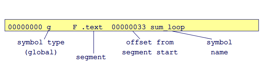
    Symbol Table one Row example

    The above picture shows an example, how symbol table is storing information about the references of functions and variables. ‘00000000’ is just the serial number. ‘00000033’ is a location relative to this section (.text) only, ‘g’ tell the symbol type and in this case, it is global. ‘.text’ is the segment name, You can extract similar information from an object file (.o file) by running the following command.

    For example,

    the above line will dump content from main.o into main.txt, which you can open and analyze in any text editor. To Read more about object file I would suggest you read this.

    Linking it all together.

    Linker’s job is to take all the object file as input and resolve references (function calls and variable names) between them and generate a final object file. The final object file contains all the code, which is required for a program to work correctly without any dependency on any other file.

    Now from this point in time, the final object can be executed directly in OS environment where memory management will be taken care by OS itself. But for an embedded processor, Once more step is required which is called memory relocation. Memory relocator maps the different sections in object file into absolute memory location as per the rules specified by “linker script file” or “ld file”.

    Generally, nowadays, Linker and Relocator are combined into a single program called “ld”, which does both the task of linking and relocation.

    By manupulating the ld file, one can easily configure which section goes into which region of memory.

    Now, As you have the basic background of the compilation process and what compiler and linker do? Lets now understand how we can tell the linker to place code & data from object files into the required memory location. Let understand the linker script.

    Primarily, There are 3 things to understand in linker script and it makes the basic foundation for all the functionality.

    1. Memory Region
    2. Input/Output Section
    3. Location Counter (“.” dot variable)

    Every Linker Script contains instructions, in a certain format and it a basic one shown below.

    1. ENTRY(Reset_Handler)2. /* Specify the memory areas */
    3. MEMORY
    4. {
    5. FLASH (rx) : ORIGIN = 0x8000000, LENGTH = 2048K
    6. }7. /* Define output sections */
    8. SECTIONS
    9. {10. /* The program code and other data goes into FLASH */
    11. .text:
    12. {
    13. . = ALIGN(4);
    14. *(.text) /* .text sections (code) */
    15. . = ALIGN(4);
    16. _etext = .; /*define a global symbols at end of code */
    17. } >FLASH
    18. }

    Above code snippet, shows a basic linker script and I will explain you line by line, what above code means and how you can modify as per your requirement.

    1. ENTRY(Reset_Handler)

    “ENTRY” tells the linker to set the address of the passed argument (function name is C or ASM file) i.e, Reset Handler as the starting value in PC (program counter) which tells the processor to start executing instruction right from that address. You are free to change “Reset_Handle” to the name of your own function which you would your program with start with.

    The “main” function is not the first function that gets executed in “Microcontrollers”. Before main, there are a whole lot of actions already had occurred in the background (all the initialization of essential peripheral, copying the data (variables) from flash to RAM, and clock initialization) and then Reset Handler function branches to the main function. You could find the implementation for Reset Handler in “startup” file which in most cases is in assembly language.

    If you miss ENTRY instruction, then linker figures out the entry point by the following manner.

    • the value of a target-specific symbol, if it is defined; For many targets, this is start
    • the address of the first byte of the ‘.text’ section, if present;
    • and if not anything from above, then address 0x00000000.

    2. /* Specify the memory areas */

    Line 2 shows how you can mark comment just in the same manner as you do in C file, block comment.

    Memory Region

    3. MEMORY
    4. {
    5. FLASH (rx) : ORIGIN = 0x8000000, LENGTH = 2048K
    6. }

    Line 3 to 6, Create a memory alias called “FLASH” of type read and execute, which starts from address 0x8000 0000 and expand up to 2048K locations. So, Now you can place your read-only content into memory region called “FLASH” and has a size of 2MB. You can follow the datasheet of the microcontroller and change it as per that. “r” and “x” flag at line 5 marks this memory as read-only and executable. similarly, “w” flag will make it writable also. This explains the 1st point out of 3 about the linker as mentioned above.

    Input/Output Section

    8. SECTIONS
    9. {

    This part of the script is fixed and you will find in every linker file. The enclosed information inside parenthesis (line no. 9 and line no 18) contains the information about mapping input section from other object files to a particular memory location.

    11.   .text:
    12. {
    13. . = ALIGN(4);
    14. *(.text) /* .text sections (code) */
    15. . = ALIGN(4);
    16. _etext = .; /*define a global symbols at end of code */
    17. } >FLASH

    Line 11, .text is the name of the output segment. You can specify your own name, but it is strictly recommended to stick with the standard. There are few standard names, and You can check the list, few paragraphs below.

    Line 13, . = ALIGN(4); “.” is a location counter. It is one of the essential things to understand about linker script and explained below.

    Line 14, tells the linker to copy all the “.text” sections from all the input object file to the output .text section.

    Line 17, } >FLASH directs the linker to store all the content in output .text section into FLASH memory region which is already defined as Memory region above.

    dot (.) | Location counter

    This special variable keeps the value of offset for that particular section in which its being used. Since the . always refers to a location in an output section, it may only appear in an expression within a SECTIONS command.Assigning a value to . will cause the location counter to be moved. This may be used to create holes in the output section. The location counter may never be moved backwards.ExampleSECTIONS
    {
    output :
    {
    file1(.text)
    . = . + 1000;
    file2(.text)
    . += 1000;
    file3(.text)
    } = 0x12345678;
    }
    the .text section from file1 is located at the beginning of the output section output. It is followed by a 1000 byte gap. Then the .text section from file2 appears, also with a 1000 byte gap following before the .text section from file3. The notation = 0x12345678 specifies what data to write in the gaps.Note: . actually refers to the byte offset from the start of the current containing object. Normally this is the SECTIONS statement, whose start address is 0, hence . can be used as an absolute address. If . is used inside a section description however, it refers to the byte offset from the start of that section, not an absolute address.

    Virtual Memory Address (VMA) and Load Memory Address (LMA)

    Virtual Memory Address (VMA) represents the memory location in RAM of the microcontroller, as those memory regions are volatile in nature( i.e, stored data clears when power ran out), so a copy initial data which is meant to be stored in RAM, must be kept in FLASH, and when system boots up, those data need to be copied from FLASH to RAM, to retain their initial value. you can always find this piece of code in the startup file, which generally happens to be in assembly language. This startup file is same where Reset_Handler resides and the main function gets called right here.


    Load Memory Address (LMA) usually represents the memory location which supports storing of Data and execution of INSTRUCTION and should be non-volatile in nature. Flash Memory is one of those memories available built-in into the Microcontroller, you have to refer the datasheet of the microcontroller to know the available LMAs.

  • Embedded Fail Safe Bootloader Design with STM32

    Ever wonder, how easy it is, these days to update your phone to the latest software. Another version of “Android” or “iOS” might be on its way while you are reading this post. Any seconds you can get the notification to update your device. You don’t have to change your phone to use the latest software available in the market (unless it is too old 😊).

    Let’s back to bootloader….

    The bootloader is an inevitable part of any embedded application (also called firmware). Especially, when you want to design a system which can be updated while it is in the operation or in the hand of customers. With this blog post, I will explain a bootloader which I designed to add support for the software update in an embedded device recently. But this bootloader can be used with any device and it is independent of the user application. If you want to skip to source code directly you can access it on my GitHub (Link).

    Let start with the architectural block diagram and some hardware detail of the test device.

    (Figure 1) Bootloader’s Flow Diagram

    The above sequence flow diagram illustrates the decision tree inside the bootloader, management of software update and recovery of the target device from any bad update (fail-safe). If the software is not tested carefully before pushing the update, it can cause catastrophic failure in the field. Which may lead the devices to go anything from unstable to completely unfunctional. In such a scenario, a fail-safe feature inside the bootloader can prevent the device from going unstable and help in bringing it back to anything from the basic functional state to fully functional state.

    The below picture shows the block diagram of the hardware setup required for the bootloader.

    (Figure 2) Hardware

    It is pretty straight forward hardware setup. The microcontroller (STM32) is connected to an external serial flash and some debug pins over UART coming out of controller which is required during development only.

    External flash memory is used to keep the candidate firmware (firmware to be updated). The bootloader doesn’t care about the mechanism by which candidate firmware got inside that external flash. All bootloader sees during update checkup, whether external flash contains a candidate firmware for update or not. It is the job of the user application to download the candidate firmware from the internet (FOTA) or over USB (DFU) and store it into external flash so that on next boot (a hard or soft reset) bootloader sees that candidate firmware inside the external flash and makes the update.

    Let’s dive deeper …

    In figure 1, The code flow sequence of the bootloader is very simple unless you know what’s happening inside each rectangle and rhombus box. so let’s look at them one by one.

    PowerOnReset denotes to a state of the device (or microcontroller). It is the very first state for the device to be in, Whenever the device gets the power, or its get reset by the watchdog, by pressing the external reset button, by BOR, etc.

    CheckUpdate is a procedure ( a C function) which checks if any candidate firmware is available in the external flash.

    CopyUpdate is another procedure (again a C function) which copy the candidate firmware from the external flash into the internal flash of the microcontroller. Once the firmware is copied successfully, it can start.

    CopyFailSafe copies the fail-safe firmware to the internal flash of the microcontroller. fail-safe firmware is loaded in the factory at the same time as of loading bootloader itself. So, fail-safe firmware+ bootloader are the two-piece of software which should be tested rigorously and must be bug-free before shipping from the factory. fail-safe firmware is the user application with just acceptable functionality which guarantees to run in case of total blackout. Its resides inside the internal flash of microcontroller and when required, it is copied to the user application area of the flash, from there it can boot.

    BOOT procedure is called when the bootloader is ready to hand over its controller of the device to user application. It is the last function which is executed by the bootloader till system reset.

    Retry is the collection of some variables which reside in a special section of SRAM, which can be accessed by bootloader only (can be accessed by user application also, but not required). Data inside this section survive soft resets. So the bootloader keep a retry counter (a Uin32 sized variable) inside this section of ram, which helps the bootloader to track the no. of times a user application crashed. Having that stats bootloader can spot the bad firmware.

    Okay…. Now lets checkout address mapping scheme inside the internal flash of the microcontroller.

    ( Figure 3 ) Memory Map STM32F0

    We are only interested in the main flash memory part highlighted in yellow with starting address 0x0800 0000. Though, the address scheme is totally dependent on the manufacturer and you will have to follow reference manual provided by microcontroller’s manufacturer. besides that we will also understand the role of SRAM in the process of bootloader design (not highlighted but, you can spot with address 0x20000000).

    Let start with some basic understanding about the boot sequence in a typical microcontroller.

    As soon as you power on the device, cpu inside the microcontroller look for the vector table and depending on you microcontroller’s configuration (usually a physical boot pin in STM32), the search for vector can endup in one of the may available memory option like, Flash, ROM, SRAM, sometimes secondary SRAM, etc. But almost every microcontroller end-up with Flash memory by default unless configuration is altered by the user. The vector table is a list of 32 bit wide addresses with many entries depending on the architecture. Each position (or index) in the table refer to special address. so let’s have a look at one such table below.

    (Figure 4) Vector Table

    In above picture, Vector table starts bottom to top. First entry in the table is the address of the beginning of the stack which happens to be in SRAM and the second entry is the address of reset function (usually in Flash). You should really understand this table if you want to have good understanding of boot procedure in almost any cpu in the world.

    Once cpu locates the vector table and both address, it load the first address into MSP (master stack pointer) and the second address into PC (program counter). Now cpu jump to PC and start executing instructions from there (which is running the reset function, usually written in assembly). I would rather not go in great detail (may be in another post) about what happens in reset function but I would still like to summarise thing in bullet below.

    • Copy initialised variables from Flash to SRAM.
    • Copy zeros to SRAM for non initialised variables.
    • Jump to main();

    Now that we understand how a microcontroller boot. We can continue with bootloader memory organization in Flash.

    In STM32F070, we have the flash memory of 128KB and 128KB is broken into 64 pages with the size of each page being 2KB. (if you don’t know about flash, then please read Wikipedia)

    We are going to reserve first 10 pages (20KB) for bootloader itself and remaining flash (128KB-20KB =108KB) is available for fail-safe as well as main firmware. For example if the size of fail-safe firmware (firmware to run in case of failure of main firmware) is 40KB then last 20 pages can be used to store fail-safe firmware and remaining 68 KB can be used for main firmware.

    (Figure 5) Flash Partition

    Figure 5, Represent things visually in more detail. Main Firmware partition has INF block at it start. This block hold some details (meta information) like Size of the Firmware, CRC of the Firmware and a Signature which is just a fixed number like 0x565A, and it helps bootloader recognize the validity of meta INF block. Because, it is not necessary the size of the firmware will be equal to its partition size (smaller or equal to the size of partition). It is important to store the size of the firmware. It will help the firmware calculate CRC and copy firmware from one partition to another.

    Now let’s understand the bootloader’s Flow Diagram (Figure 1)

    Now, That you have understood things like, boot procedure, vector table and flash partition. Let’s join everything together and understand the bootloader working with the help of Figure 1.

    Figure 1 (Again)

    As soon as, The device turns on, it jump to reset function of bootloader where it jumps again to main function after coping data into SRAM. In main function, it initialises the External Flash memory (see figure 2) and Runs the state machine. In state machine, it check for any update available in external flash. If it finds the update it copies the candidate firmware from external flash into “Main Firmware Partition” of internal flash and mark the update in external flash as copied so that the next time it doesn’t copy the same update again. Once the candidate firmware has been copied. It initializes the retry context (retry counter = 0) and continues the state machine from start.

    Entering the state machine loop again it rechecks for any update available and as it has already copied it earlier so, this time it doesn’t find any update in external flash and bootloader continue for next check.

    Bootloader next checks if retry context is valid. For a retry context to be valid it has a variable called “signature”, which should always be equal to a fixed magic number. If that signature is not valid then, it means that the bootloader has never initialized the retry variable and retry variable contains a garbage value. If the value of retry variable is not valid then it initializes the retry variable to zero and Boot the application.

    If retry value is valid and less than the maxmium no of allowed retry, then it increment the retry variable by 1 and Boots the application.

    Now here comes the interesting part, if the retry variable count exceeds the maximum no of allowed retry, then bootloader will assume that the main firmware is faulty and it copies the fail-safe firmware from fail-safe partition to main-firmware partition after earsing the main-firmware partition and as well as initializes the retry variable to zero and state machine starts from begining.

    Boot the application …

    Booting the application involves couple of actions, and they are listed below in bullets.

    • Initialize the watchdog.
    • Remap the vector table — because cpu currently points to the vector table of the bootloader. We have to remap it to point the cpu to new vector table of application. (see the code for implementation).
    • set the MSP (master stack pointer) from new vector table.
    • and Jump to new PC (program counter).

    How bootloader spot the bad firmware ?

    As soon as, application boots, the application firmware must feed the bootloader on the regular time interval (max 6s). If it fails to do so, then watchdog will reset the controller and bootloader will kick back in, once the bootloader state machine starts again it will check for retry variable count before booting the main firmware again. If this phenomena of reseting microcontroller by watchdog happen more than the maximum allowed value (max retry count), then the firmware is spotted BAD.

    You can checkout the source code — (Here)